Table of Contents
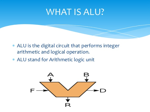
ALU(Arithmetic Logic Unit) is a digital circuit used to function arithmetic and logic operations. It performs the fundamental building block of the central processing unit (CPU) of a computer. present-day CPUs contain very powerful and complex ALUs. In addition to ALUs, modern CPUs contain a control unit (CU). Most of the operations of a CPU are function by one or more ALUs, which load data from input registers. A register is a small amount of storage accessible as part of a CPU. The control unit tells the ALU what operation to perform on that data, and the Arithmetic Logic Unit stores the result in an output register.
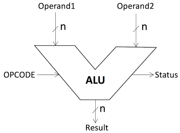
The control unit moves the data between these registers, the ALU, and memory. The inputs to an ALU are the data to be regulated on, called operands, and code points out the operation to be performed; the ALU’s output is the result of the performed operation. In many designs, the ALU also has status inputs or outputs, or both, which convey instruction about a previous operation or the current operation, respectively, between the ALU and external status registers.
ALU(Arithmetic Logic Unit)
An arithmetic logic unit (ALU) is a conjunctional digital auto electronic circuit that performs arithmetic and bitwise affair on integer binary numbers. This is in contrast to a floating-point unit (FPU), which operates on floating-point numbers. An ALU is a major building block of many types of computing routes, including the central processing unit (CPU) of computers, FPUs, and computer graphics handle units (GPUs). A single CPU, FPU or GPU may contain multiple ALUs.
Signals
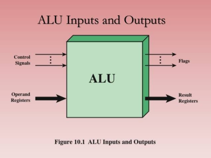
An ALU has a variety of input and output nets, which are the electrical conductors used to convey digital signals between the ALU and external circuitry. When an ALU is operating, external circuits apply signals to the ALU inputs and, in response, the ALU produces and conveys signals to external circuitry via its outputs.
Data
A basic ALU has three parallel data buses subsist of two input operands (A and B) and a result output (Y). Each data bus is a group of signals that conveys one binary integer number. Typically, the A, B and Y bus widths (the number of signals comprising each bus) are identical and match the native word size of the external circuitry.
Opcode
The opcode input is a parallel bus that transmits to the ALU an operation option code, which is an enumerated value that specifies the desired arithmetic or logic operation to be performed by the ALU. The opcode size (its bus width) resolve the maximum number of different operations the ALU can function; for example, a four-bit opcode can specify up to sixteen different ALU operations. Generally, an ALU opcode is not the same as a machine language opcode, nevertheless, in some cases, it may be directly encoded as a bit field within a machine language opcode
Status
Outputs
The status outputs are various individual signals that transmit supporting information about the result of the current ALU operation. General-purpose ALUs commonly have status signals such as:
Carry-out, which conveys the carry emerge from an addition operation, the borrow resulting from a subtraction operation, or the overflow bit resulting from a binary shift operation.
Zero, which expresses all bits of Y are logic zero.
Negative, which expresses the result of an arithmetic operation is negative.
Overflow, which expresses the result of an arithmetic operation has exceeded the numeric range of Y.
Parity, which expresses whether an even or odd number of bits in Y is logic one.
At the end of each ALU operation, the status output signals are usually stored in external registers to make them available for future ALU operations (e.g., to implement multiple-precision arithmetic) or for controlling conditional branching. The collection of bit registers that store the status outputs are often treated as a single, multi-bit register, which is referred to as the “status register” or “condition code register”.
Inputs
The status inputs allow additional information to be made available to the ALU when performing an operation. Typically, this is a single “carry-in” bit that is the stored carry-out from a previous ALU operation.
ALU Elements
Functional Elements
A typical digital computer system has four basic functional elements
(1) input-output equipment,
(2) main memory,
(3) the control unit
(4) arithmetic-logic unit
Any of a number of devices is used to enter data and program instructions into a computer and to gain access to the results of the processing operation. Common input devices include keyboards and optical scanners; output devices include printers and monitors. The information received by a computer from its input unit is stored in the main memory or, if not for immediate use, in an auxiliary storage device. The control unit selects and calls up instructions from the memory in the appropriate sequence and relays the proper commands to the appropriate unit.
It also synchronizes the varied operating speeds of the input and output devices to that of the arithmetic-logic unit so as to ensure the proper movement of data through the entire computer system. The ALU performs the arithmetic and logic algorithms selected to process the incoming data at extremely high speeds in many cases in nanoseconds (billionths of a second). The main memory, control unit, and ALU together make up the central processing unit (CPU) of most digital computer systems, while the input-output devices and auxiliary storage units constitute peripheral equipment.
Central processing unit
The CPU provides the circuits that implement the computer’s instruction set its machine language. It is composed of an arithmetic-logic unit and control circuits. The ALU carries out basic arithmetic and logic operations, and the control section determines the sequence of operations, including branch instructions that transfer control from one part of a program to another. Although the main memory was once considered part of the CPU, today it is regarded as separate. The boundaries shift, however, and CPU chips now also contain some high-speed cache memory where data and instructions are temporarily stored for fast access.
The Arithmetic Logic Unit has circuits that add, subtract, multiply, and divide two arithmetic values, as well as circuits for logic operations such as AND and OR (where a 1 is interpreted as true and a 0 as false, so that, for instance, 1 AND 0 = 0; see Boolean algebra). The ALU has several to more than a hundred registers that temporarily hold results of its computations for further arithmetic operations or for transfer to main memory.
The circuits in the CPU control section provide branch instructions, which make elementary decisions about what instruction to execute next. For example, a branch instruction might be “If the result of the last ALU operation is negative, jump to location A in the program; otherwise, continue with the following instruction.” Such instructions allow “if-then-else” decisions in a program and execution of a sequence of instructions, such as a “while-loop” that repeatedly does some set of instructions while some condition is met. A related instruction is the subroutine call, which transfers execution to a subprogram and then, after the subprogram finishes, returns to the main program where it left off.
What component of a processor holds instructions waiting to be processed by the ALU?
CPU components are not the easiest ones to understand. There is simply way too much going on in those tiny little things. An aspiring student of CPU may ask what component of a processor that holds instructions waiting to be processed by the ALU?
The simple answer is Cache Levels or RAM. However, RAM is not part of the Processor; the Cache Level Memories are PART of the processor. Another in-depth perspective would tell you that it is stored in Registers. Specifically, the Accumulator Registers. The immediate place where the Arithmetic Logic Unit fetches data from is the registers. Before Accumulators, the instruction is stored in Current Instruction Registers and before that, it is moved to Memory Data Registers and Before that, it is stored in either Cache Memory or RAM. I am sure I have confused you. In short, here are the steps:
Steps for Instructions to Reach ALU
Generally, the following components are activated in sequence before the instruction/data reaches the ALU.
- Cache/RAM
- Memory Data Registers
- Current Instruction Registers
- CPU
- Accumulator Register
- ALU
As you can see, the component that holds data JUST before ALU is NOT the Cache/RAM, it is the Accumulator Register.